
How Do Tolerances Shape the Accuracy of Modern 3D Printing Technology
Key Features
- Different 3D printing methods (FDM, SLA, SLS, MJF, DMLS) have varying tolerance ranges, from ±0.1 mm in SLA to ±0.3 mm in FDM.
- Plastics, resins, and metals expand and contract differently, directly affecting tolerance outcomes.
- Complex geometries, wall thickness, and unsupported overhangs significantly influence achievable accuracy.
- Finishing processes such as sanding, heat treatment, or machining can improve or slightly alter final tolerances.
Have you ever wondered why two parts printed on the same 3D printer using the same file, sometimes don’t fit together perfectly? The answer lies in 3D printing tolerances, the hidden factor that decides whether your model snaps together seamlessly or needs extra filing and rework. In today’s manufacturing world, where industries are moving from prototyping to end-use parts, tolerances have become just as critical in additive manufacturing as they are in traditional machining.
Quick Answer
3D printing tolerances define the acceptable dimensional variation between the CAD model and the printed part. They depend on the printer technology, material, and post-processing.
According to Wohlers Report 2023, the additive manufacturing industry surpassed $18 billion globally, with an annual growth rate of 21%. A growing portion of this value comes from end-use functional parts, not just prototypes. However, as production shifts to larger volumes, tolerance consistency has emerged as a top design and engineering challenge. Research from ASTM International (2024) indicates that dimensional accuracy discrepancies of 0.1–0.4 mm are common across consumer-grade printers, while industrial systems can achieve near-CNC levels at ±0.025 mm.
This raises a fundamental question for designers and engineers: how do we predict, control, and optimize tolerances in additive manufacturing? Without clear understanding, even a well-designed part can fail in fit, assembly, or performance. That’s why industries such as aerospace, medical devices, and automotive invest heavily in tolerance testing and standardization. By 2030, analysts project that over 40% of 3D-printed parts in production environments will require tolerance verification standards similar to ISO 2768 for machining.
What Are Tolerances in 3D Printing?
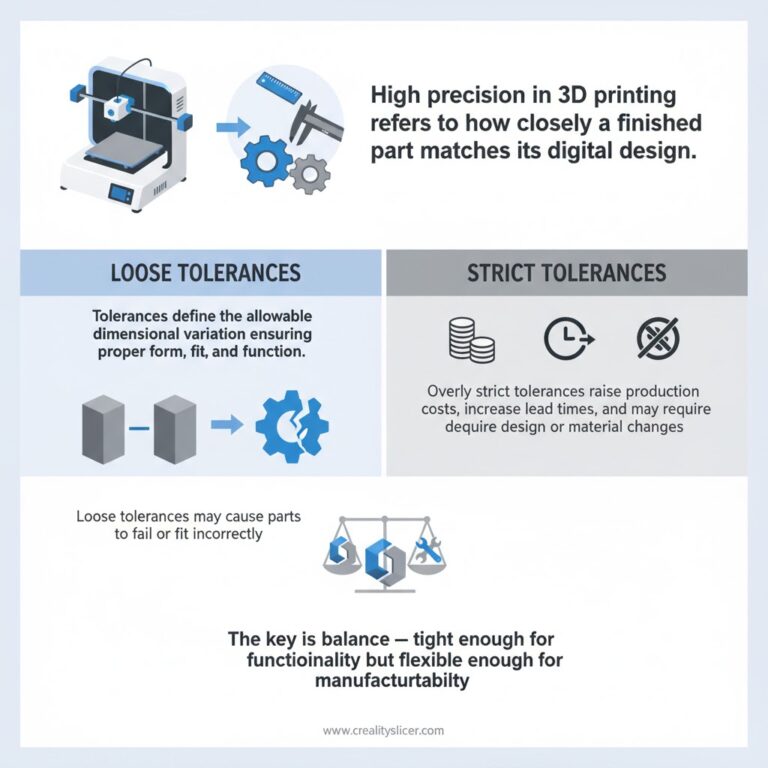
High precision in 3D printing refers to how closely a finished part matches its intended digital design. Tolerances define the allowable dimensional variation that ensures parts can achieve proper form, fit, and function. If tolerances are set too loose, components may fail to work as designed or fit correctly with their counterparts.
On the other hand, making tolerances overly strict can increase production costs, extend lead times, or even force changes to part geometry, materials, or processes. For 3D-printed parts, finding the right balance is essential, tight enough to guarantee functionality, but not so rigid that it limits manufacturability.
What Should You Expect From Tolerances in 3D Printing?
Different 3D printing technologies deliver varying levels of accuracy when it comes to tolerances. The final precision depends not only on the printer but also on part size, geometry, and material choice. Larger and bulkier components typically face more shrinkage during the printing and cooling process.
While post-processing steps such as machining, sanding, or heat treatment can improve dimensional accuracy, achieving tight tolerances on the first print is not always guaranteed. That’s why many manufacturers recommend producing a sample part first, allowing necessary adjustments before full production runs.
Below is a breakdown of typical tolerances achieved with the most widely used 3D printing methods. These figures are indicative, as results may vary depending on part design, wall thickness, and chosen material.
| 3D Printing Technology | Typical Tolerance |
| MJF (Multi Jet Fusion) | ± 0.3% (± 0.2 mm) |
| SLS (Selective Laser Sintering) | ± 0.3% (± 0.3 mm) |
| SLA (Stereolithography) | ± 0.5% (± 0.2 mm) |
| FDM (Fused Deposition Modeling) | ± 0.5% (± 0.5 mm) |
| Carbon DLS | ± 0.1% (± 0.1 mm) |
| DMLS (Direct Metal Laser Sintering) | ± 0.2% (± 0.1–0.2 mm) |
| PolyJet | ±0.1 mm initially, plus ±0.05 mm for every additional 10 mm |
MJF (Multi Jet Fusion) Tolerances
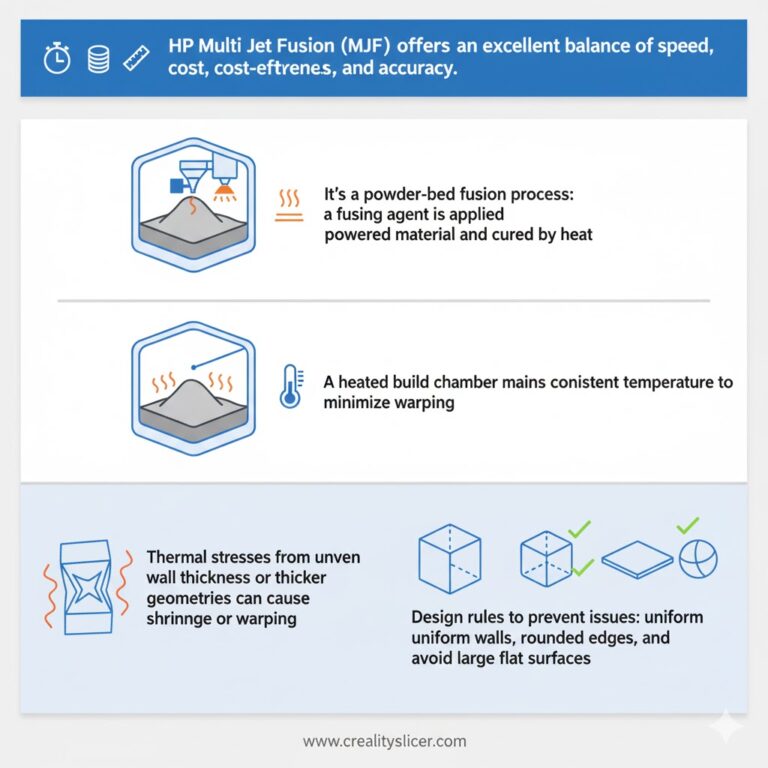
HP Multi Jet Fusion (MJF) is valued for its balance of speed, cost-effectiveness, and accuracy. This powder-bed fusion process applies a fusing agent to powdered material, which is then cured by a heat source. A heated build chamber minimizes warping by keeping the entire powder bed at a stable temperature.
Still, thermal stresses caused by uneven wall thicknesses or thicker geometries can result in shrinkage or warping. Following injection-molding design rules—uniform walls, rounded edges, and avoiding large flat surfaces—helps reduce these risks.
| Parameter | Value |
| Tolerance | ± 0.3% (min ± 0.3 mm) |
| Shrinkage | Typically 2–3%, but most MJF printers compensate automatically |
| Build Volume | Up to 380 × 284 × 380 mm (recommended max: 356 × 280 × 356 mm) |
| Layer Thickness | ~0.08 mm |
| Minimum Feature Size | 0.5 mm (0.7 mm recommended) |
| Support Structure | Not required |
Pro Tip
For tighter tolerances, use PA 12 glass-filled material.
SLS (Selective Laser Sintering) Tolerances
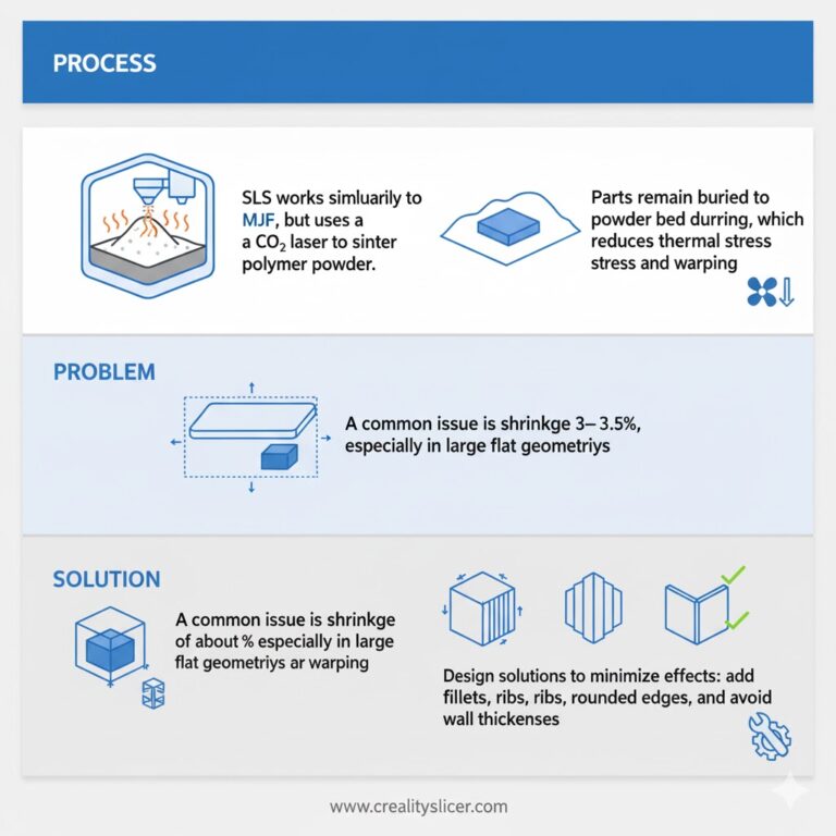
SLS works similarly to MJF, but instead of heat lamps, it uses a CO₂ laser to sinter polymer powder. One advantage of SLS is that printed parts remain buried in the powder bed during cooling, reducing thermal stress and warping.
However, shrinkage of 3–3.5% is common, particularly for large flat geometries. Designers can minimize these effects by incorporating fillets, ribs, and balanced wall thicknesses.
| Parameter | Value |
| Tolerance | ± 0.3% (± 0.3 mm for 100 mm) |
| Shrinkage | 3–3.5% typical |
| Build Volume | Up to 340 × 340 × 605 mm (recommended: 320 × 320 × 580 mm) |
| Layer Thickness | ~0.1 mm |
| Minimum Feature Size | 0.5 mm (0.75 mm recommended) |
| Support Structure | Not required |
Pro Tip
Glass-filled PA 12 helps reduce warping and improves dimensional stability.
SLA (Stereolithography) Tolerances
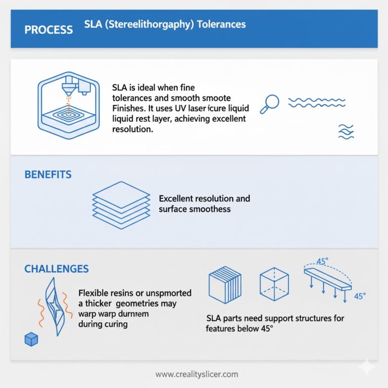
SLA excels when fine tolerances and smooth surface finishes are critical. It uses a UV laser to cure liquid resin layer by layer, delivering excellent resolution. However, flexible resins or unsupported geometries can warp during curing. SLA parts also require support structures for features below 45°.
| Parameter | Value |
| Tolerance | ± 0.5% (± 0.20 mm) |
| Shrinkage | Unsupported features may warp |
| Build Volume | Up to 736 × 635 × 533 mm |
| Layer Thickness | ~0.02 mm |
| Minimum Feature Size | 0.1 mm |
| Support Structure | Required for overhangs |
Best For: Dental, jewelry, medical, and precision prototypes.
FDM (Fused Deposition Modeling) Tolerances
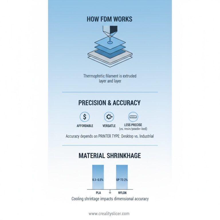
FDM printers extrude thermoplastic filament layer by layer. While versatile and cost-effective, FDM offers the least precise tolerances compared to resin or powder-bed processes.
Dimensional accuracy can vary widely depending on the printer (desktop vs. industrial) and material. Cooling shrinkage is a major factor: PLA shrinks by just 0.3–0.5%, while Nylon may shrink up to 2%.
| Parameter | Value |
| Tolerance (Desktop) | ± 0.5% (min ± 0.5 mm) |
| Tolerance (Industrial) | ± 0.15% (min ± 0.2 mm) |
| Shrinkage | PLA ~0.5%, Nylon 12 up to 2%, PVDF up to 4% |
| Build Volume | Up to 914 × 610 × 914 mm |
| Layer Thickness | 0.05–0.3 mm |
| Minimum Feature Size | ~0.2 mm |
DMLS (Direct Metal Laser Sintering) Tolerances
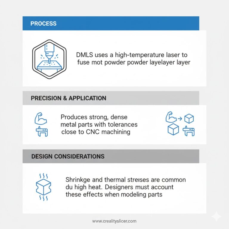
DMLS is the go-to technology for functional metal parts, offering strong, dense components with tolerances approaching those of CNC machining. Since it involves high-temperature laser fusion, shrinkage and thermal stresses are common and must be considered in design.
| Parameter | Value |
| Tolerance | ± 0.2% (± 0.1–0.2 mm) |
| Shrinkage | Likely due to high heat input |
| Build Volume | Up to 250 × 250 × 325 mm |
| Layer Thickness | 0.02–0.08 mm |
| Minimum Feature Size | 0.75 mm cosmetic, 1.5 mm structural |
| Support Structure | Required |
Note: Post-machining is often applied to achieve critical fits and fine tolerances.
PolyJet Tolerances
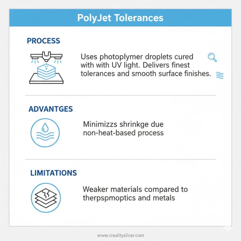
PolyJet offers some of the finest tolerances and smoothest surface finishes in 3D printing. Unlike heat-based processes, it jets photopolymer droplets cured with UV light, minimizing shrinkage. However, the materials are not as strong as thermoplastics or metals.
| Parameter | Value |
| Tolerance | ± 0.05–0.1 mm (for 100 mm) |
| Shrinkage | Minimal, slight warping possible on large flat areas |
| Build Volume | Up to 490 × 391 × 200 mm |
| Layer Thickness | 0.004 mm |
| Minimum Feature Size | 1.2 mm rigid, 2 mm flexible |
| Support Structure | Required |
Best For: Prototypes requiring detail and visual validation.
Carbon DLS Tolerances
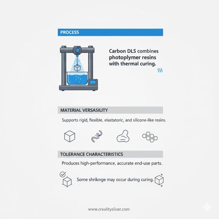
Carbon’s Digital Light Synthesis (DLS) combines photopolymer resins with thermal curing, producing high-performance end-use parts. It supports a variety of resins, rigid, flexible, elastomeric, and silicone-like. While highly accurate, some shrinkage can occur during curing.
| Parameter | Value |
| Tolerance | ±0.1% (± 0.1 mm per 100 mm) |
| Shrinkage | Minor, due to curing |
| Build Volume | Up to 119 × 189 × 300 mm (recommended ≤ 100 × 100 × 150 mm) |
| Layer Thickness | ~0.1 mm |
| Minimum Feature Size | ≥ 1 mm |
| Support Structure | Required |
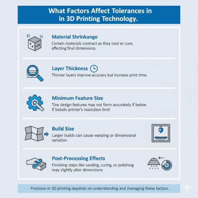
What Factors Affect Tolerances in 3D Printing Technology?
In 3D printing, tolerances are shaped by multiple factors which determine the precision and consistency of the final part.
Material Shrinkage
Different materials expand and contract at varying rates during heating and cooling, directly impacting dimensional accuracy. Thermoplastics like Nylon can shrink up to 2–3%, while PLA shows less than 0.5% shrinkage. Without proper compensation in design, this can lead to parts that are undersized, warped, or distorted.
Layer Thickness
The thickness of each printed layer determines how closely the part matches the digital CAD model. Finer layers (e.g., 0.02 mm in SLA) achieve higher resolution and smoother surfaces, but they also increase print time. Thicker layers, while faster, can introduce more visible deviations in tolerance.
Minimum Feature Size
Each 3D printing technology has a minimum feature size it can reliably produce. For instance, SLA can print details as small as 0.1 mm, while FDM may struggle below 0.2 mm. Designing features smaller than the printer’s capability often results in incomplete or inaccurate details.
Build Size
Larger builds are more prone to tolerance deviations due to heat distribution and material shrinkage across the volume. For example, an FDM printer producing parts over 300 mm may show more warping and dimensional drift compared to smaller parts. Staying within recommended build limits helps improve accuracy.
Post-Processing Effects
Finishing techniques like sanding, vapor smoothing, or machining improve surface finish but can slightly alter tolerances. For critical components, post-processing should be carefully controlled, as even removing 0.05–0.1 mm of material can affect assembly fit and part performance.
What Strategies Improve 3D Printing Tolerances?
Improving 3D printing tolerances requires a mix of smart design choices, precise machine calibration, suitable material selection, and hybrid processes that enhance accuracy.
Design for Additive Manufacturing (DfAM)
Incorporating tolerance considerations during the CAD stage helps reduce errors later in the process. By designing with allowances for shrinkage, clearance, and support placement, engineers can achieve more consistent dimensional accuracy.
Printer Calibration and Maintenance
Well-calibrated machines deliver tighter tolerances. Regular alignment of printer axes, nozzle inspection, and software updates ensure the system performs at its best, reducing deviations across multiple builds.
Material Selection
The choice of material plays a critical role in accuracy. Low-shrinkage polymers and stable resins are ideal for high-precision applications, while metals often require careful planning to offset heat-induced warping.
Hybrid Manufacturing Approach
Combining additive manufacturing with CNC machining offers the best of both worlds, complex geometries with precise tolerances. According to a 2025 SME survey, hybrid workflows reduced tolerance errors by nearly 45% compared to additive-only processes.
Final Words
As 3D printing continues to evolve, tolerances will play an even greater role in bridging the gap between prototyping and full-scale production. Emerging advancements like AI-driven print monitoring, real-time error correction, and adaptive slicing algorithms are already reshaping how precision is achieved. For businesses and designers, staying ahead means not only understanding today’s tolerance capabilities but also preparing for tomorrow’s innovations that will make additive manufacturing more reliable, scalable, and production-ready than ever before.

Hi, I’m Mark Stevens. I love exploring 3D printing and diving deep into slicer software. I spend my time testing slicer settings, comparing features, and sharing tips to help creators get smoother, faster, and more reliable prints. My goal is to make slicer tools easy to understand and use, whether you’re a beginner or a seasoned 3D-printing enthusiast.


